1/24 Chassis Idea
Posted: Thu 7. Feb 2013 15:30
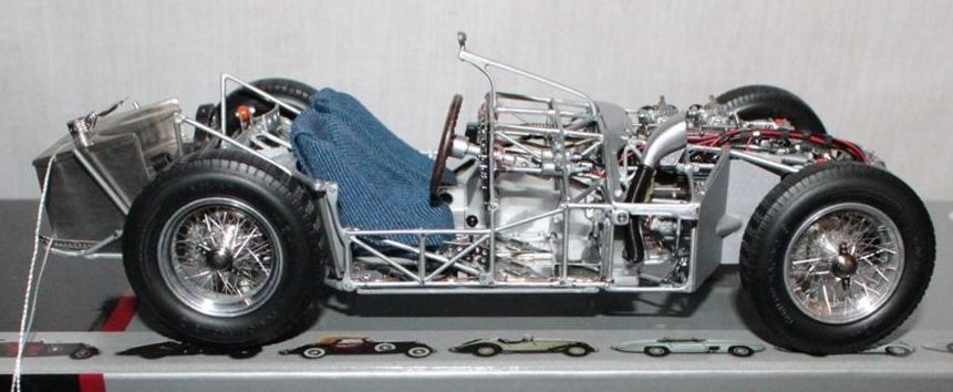
I was going to wait until I was a little further along but decided to post this 1/24 chassis that I am gearing up for. So far it is only at the drawing stage but I have a body and wheels coming in the mail to begin construction very soon. I fooled around trying to make 1/32 slot car stuff work with Wes's set up but it is a pretty tight trying to fit the batteries and electonic components in a scale classic 1/32 body. It can be done with larger car like Nascars but classic sports cars are a hard nut to crack. I figured why not try 1/24? With that in mind, I ordered two 1/24 vacuform bodies from Pattos Place in Australia, a Maserati Tipo 61 Birdcage and a Chaparral 1. I picked up two full sets of Dynamic 1/24 slot car wheels on Ebay. When all of the parts get here I will start building. I plan to build my own spindles from soldered brass parts but I will try to use Wes's steering coil and receiver unit. I will use a C can motor from a tooth brush which was designed to run on 3 volts in the tooth brush. Here are some drawings.
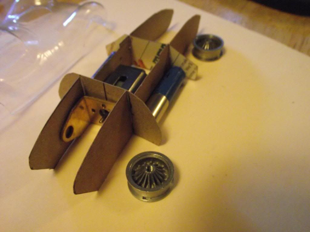
The chassis will be built from balsa wood, in a manner similar to model airplane construction the bulkhead pieces will be cut to the inside contours of the body minus a few cm to allow installing foam to cushion the body on the chassis.
This one has simple front axle beams.
This drawing shows a slightly more sophisticated axle beam set up. It is designed to rock slightly in the chassis. It is my hope that having a small amount of articulation will allow me to build tracks with camber changes in them. Some articulation in the suspension will enable the mag tiller to maintain close contact with the wire. Allowing a track with a Corkscrew? The car will use two batteries wired in parallel so will retain the stock voltage for the electronics. They will mount longwise on both sides of the chassis.
The 1/24 car would allow both sidewinder and inline motor set ups. This drawing shows the motor mounted behind the axle which is common in RC cars because the mass of the batteries and steering components offset the rear motor weight.
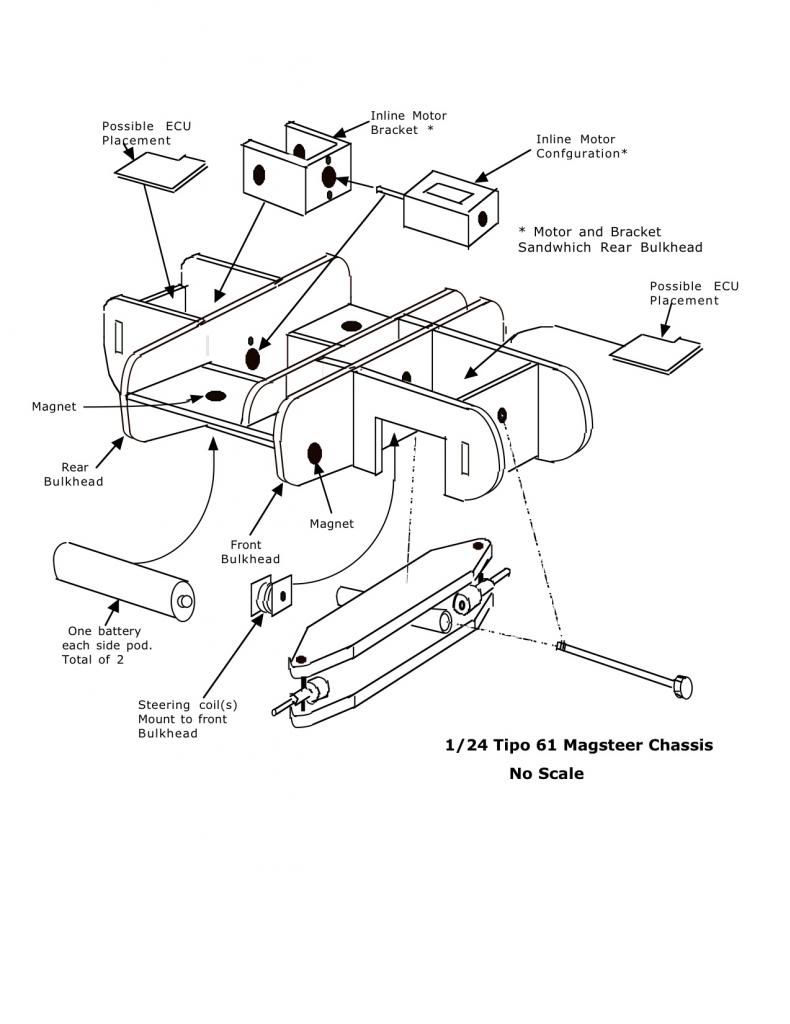
Here is an inline motor set up.
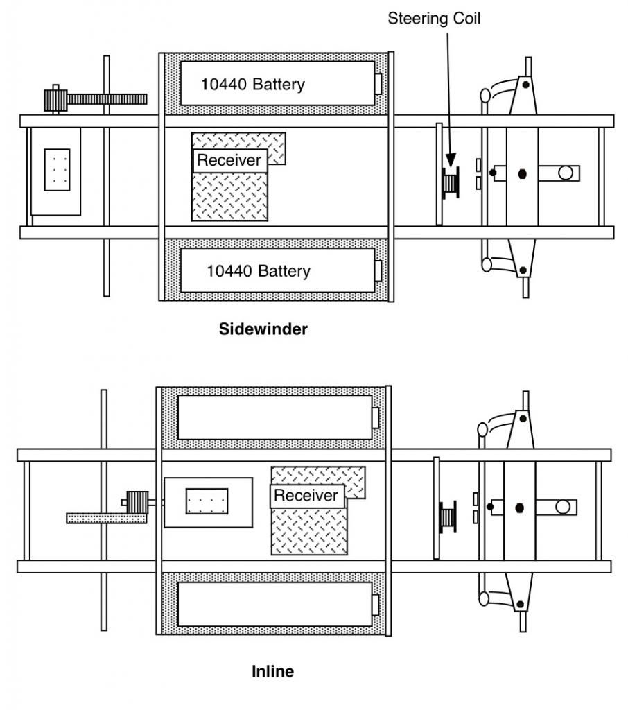
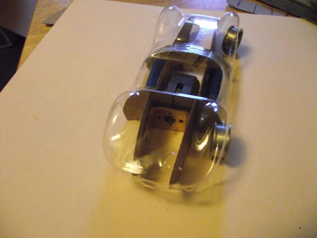
Overhead views of the two motor mounting set ups. In the picture it appears the dark panels are under the batteries. In reality they would be above the batteries with magnets installed in holes in the panel to both retain the batter and provide electrical contacts similar to Wes's design.
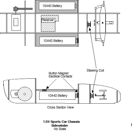
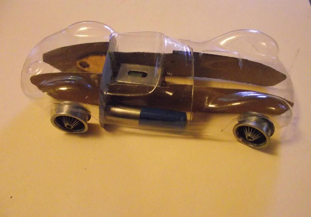
Here is a side view of a sidewinder set up.
Mike
The chassis will be built from balsa wood, in a manner similar to model airplane construction the bulkhead pieces will be cut to the inside contours of the body minus a few cm to allow installing foam to cushion the body on the chassis.
This one has simple front axle beams.
This drawing shows a slightly more sophisticated axle beam set up. It is designed to rock slightly in the chassis. It is my hope that having a small amount of articulation will allow me to build tracks with camber changes in them. Some articulation in the suspension will enable the mag tiller to maintain close contact with the wire. Allowing a track with a Corkscrew? The car will use two batteries wired in parallel so will retain the stock voltage for the electronics. They will mount longwise on both sides of the chassis.
The 1/24 car would allow both sidewinder and inline motor set ups. This drawing shows the motor mounted behind the axle which is common in RC cars because the mass of the batteries and steering components offset the rear motor weight.
Here is an inline motor set up.
Overhead views of the two motor mounting set ups. In the picture it appears the dark panels are under the batteries. In reality they would be above the batteries with magnets installed in holes in the panel to both retain the batter and provide electrical contacts similar to Wes's design.
Here is a side view of a sidewinder set up.
Mike