Part 6: Assembling Frontend Kit
1. Determine the correct orientation of the polarity of the two neodymium 5mm dia x 3mm thick magnets to be glued into the box on the tie rod. It is important that the polarity of both magnets is oriented correctly, when glued into the box.
- A. If you have an operational stock magracer:
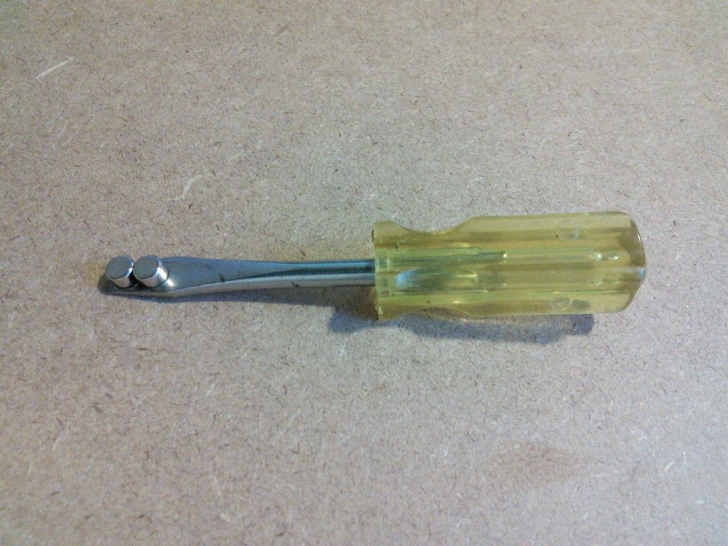
- 1. Place 2 magnets side by side on the blade of a screwdriver as depicted in the photo below.
- 2. Now with your thumb and index finger, take a hold of the magnet box on your stock magracer, and place the magnets stuck to the screwdriver against the back of the magnet box. If the magnets are oriented properly on the screwdriver, they will quickly snap toward the magnets in the stock magracer and easily line up as shown in the photo below.
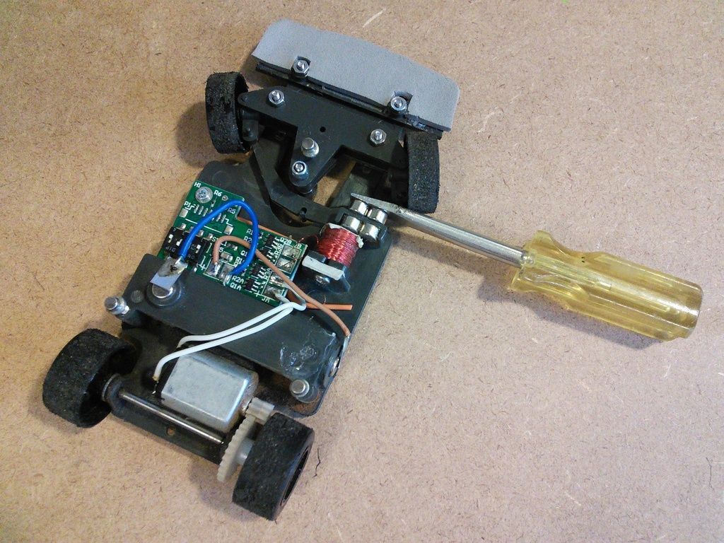
- 3. If they don’t want to line up easily, the magnets on the screwdriver are not oriented properly. Change the orientation and try again.
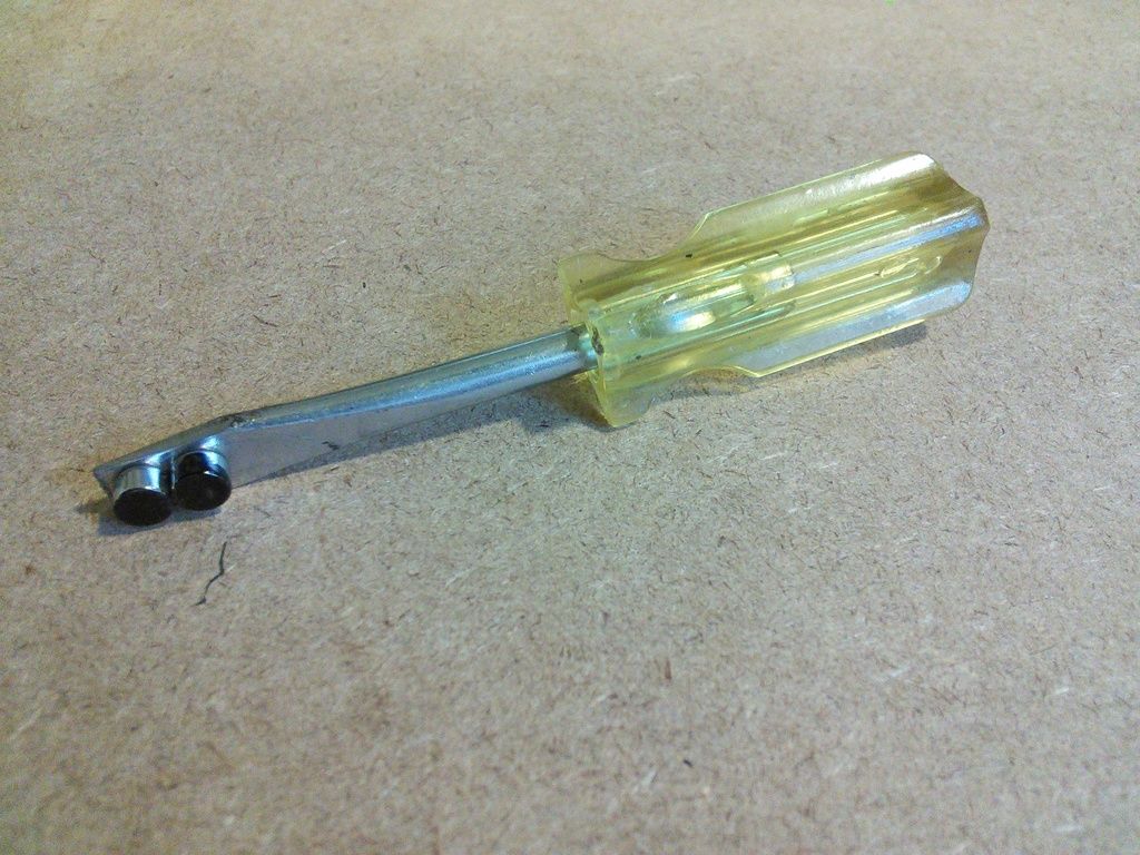
4. Once they are oriented properly, mark the exposed faces of the 2 magnets on the screwdriver with a black permanent felt tip pen. Also mark the top edge of one of the magnets to distinguish between left and right as shown in the photo below.
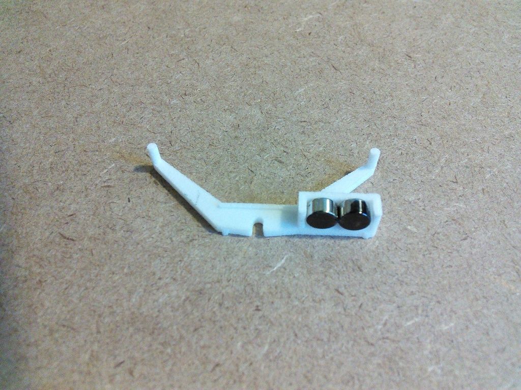
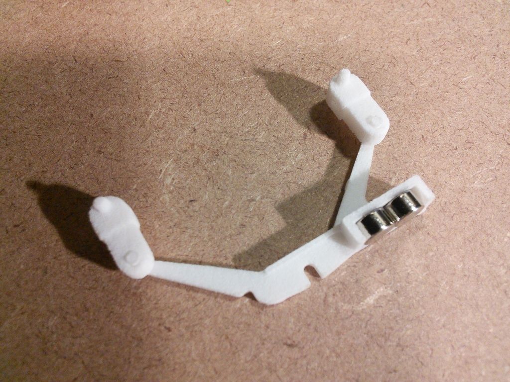
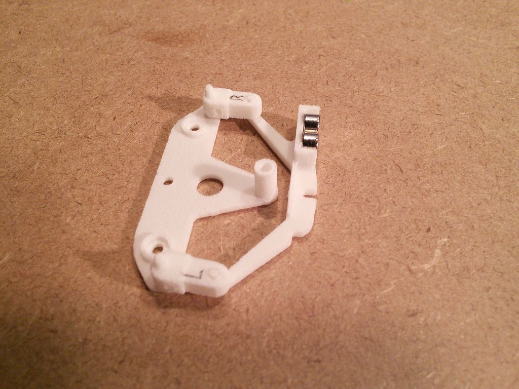
- 5. Now that you have determined the correct orientation for the magnets, simultaneously glue them into the box on the tie rod. Make certain that they are both oriented the same way in the box as in the stock magracer, with the black faces facing as depicted in the photo below. Be careful not to switch the left and right magnets. When gluing the magnets in place, make sure that they are firmly pressed to the bottom and back of the box. CA glue such as Krazy Glue or Supper Glue works well for this. Two part epoxy adhesive also works.
- B. If you do not have an operational magracer:
- 1. You're in trouble

- 2. Not really! If you have a stock tie rod with magnets installed, use that as your model for comparison, and follow the instructions above.
- 3. If you don't have anything with which to compare, you have a 50% of getting it right! Just glue 2 magnets in the box. Make sure that they are firmly pressed to the bottom and back of the box. CA glue such as Krazy Glue or Supper Glue works well for this. If they are oriented the wrong way, the car will steer the wrong way. In that case just swap the coil wiring on the PCB and you're good to go.

2. Ream out the hole farthest from the kingpins, in each of the stub axle carriers (steering knuckles) using a #50 (.070”) (1.78mm) drill bit held in a pin vice (small handheld manual drill). (The steering knuckles are symmetrical and the 3D model for the left one is identical to the right one.) Now check to see if the pins at each end of the steering plate (tie rod) will fit into the holes that you just enlarged in the steering knuckles. An easy and safe way to do this is to first place the tie rod on a smooth flat surface, with the pins facing up. Then with the finger of one hand, hold down the tie rod. Now with the thumb and index finger of the other hand, (or a pair of tweezers) grasp a knuckle near the hole you enlarged. Slip the hole in the knuckle over the pin on the tie rod. Be very careful doing this so as to not break the pin off of the tie rod. A pair of tweezers comes in handy for this. Do NOT try to force the pin into the hole. Do the same with the other knuckle and pin.
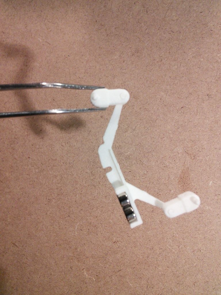
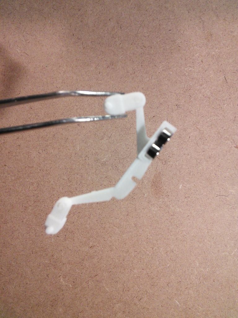
3. The knuckles should rotate freely on the pins of the tie rod but without any play (without any slop). If they don’t rotate freely, ream out the hole a little more with the same bit. Do not use a bit larger than #50. Just run a #50 bit back and forth through the hole from both sides. Continue reaming out the hole from both the top and bottom until it is just the right size. The best hole diameter is usually about .003” larger than the pin diameter. When the knuckle is held as shown, the tie rod should should swing freely and come to rest as depicted in the photos below.
4. Now put the upper and lower suspension beams together.
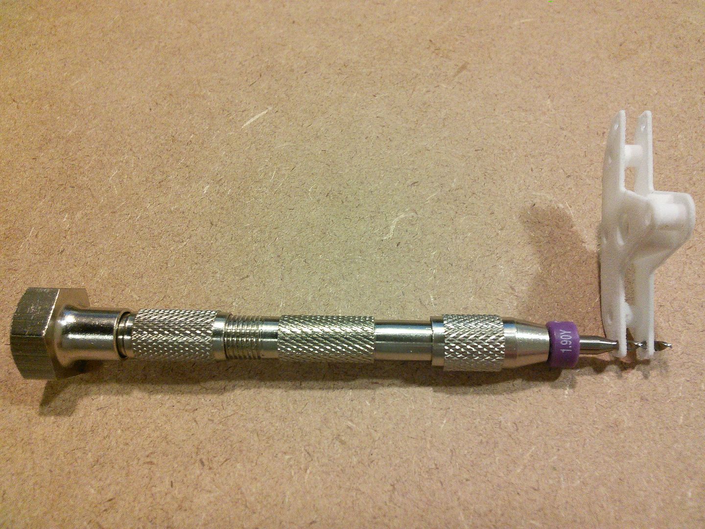
Simultaneously ream out the holes at the end of the beams with a 1.90mm (.0748”) bit. See photo below.
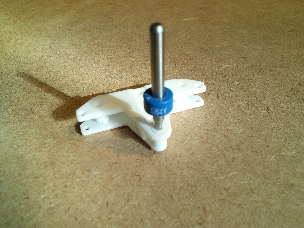
5. After that, with the upper and lower beams still held together, ream out the hole in the lower beam that is used to attach the guide arm to the beams. Use a 5/64” diameter drill bit held in a pin vice to do this. See photo below.
6. Now separate the upper and lower suspension plates (beams) and check to see if the king pins of the steering knuckles fit into the corresponding holes at the end of the lower suspension beam. An easy way to do this is to first place the lower beam on a smooth flat surface. With the steering knuckles attached to the tie rod, place the pin of one of the knuckles, into one of the holes at the end of the lower beam. Do the same with the other knuckle. Label the knuckles Left and Right so you can put them back together the same way.
7. Now place the upper beam over the lower beam and knuckles, being careful to align the pins of the knuckles with the holes in the upper beam. Press the lower and upper beams together. The knuckles, with the tie rod attached, should rotate freely between the beams when the beams are squeezed together in the middle. If they don’t, remove the knuckles, put the upper and lower beams back together again, and ream out the holes again at both ends
simultaneously with a #48 (.760”) bit.
When reaming out the holes at the ends of the beams, only do so when both beams are held together so that the holes in the upper and lower beams can be reamed out simultaneously to maintain the proper alignment.
8. Verify that your front wheels spin freely on the stock front stub axles. If not, correct this before proceeding.
9. Now disassemble the beams, knuckles, and tie rod. Put a stock stub axle through the bore of a front wheel and press the axle into a hole in the steering knuckle. Ream out the hole first with a #53 (.0595”) (1.51mm) drill bit, which should be large enough for the .0625” diameter axle. Leave about .005” of clearance between the hub of the wheel and the side of the knuckle, so the wheels spin freely.
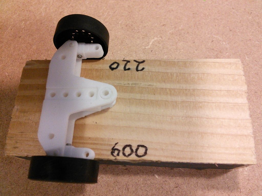
10. Attach the knuckles, with the front axles and wheels, to the upper and lower suspension beams. An easy way to do this is to place the lower beam across a block of wood 1.50” - 1.60” wide and about ½” thick and 3” long. Place the bottom pin of each knuckle in a hole at the end of the beam. Then place the upper beam on top making sure to line up the pins of the knuckles with the holes in the beam. If you have trouble keeping these pieces together, you may want to put a small,
very thin piece of double faced tape in the middle of the lower beam, before placing the upper beam on top. Press the upper and lower beams together with the steering knuckles and wheels attached and set this aside.
11. Now press a neodymium 4mm dia x 3mm thick magnet into the guide arm. Make sure that the magnet is oriented so that the polarity is the same as that of the two 3mm dia x 2mm magnets pressed into the frame earlier. All 3 magnets must be orientated the same way, either all with the positive (+) pole facing up, or all with the negative (-) pole facing up. The bottom of the magnet should protrude about .010” - .015” below the bottom of the guide arm. A 4mm x 3.25mm magnet should also work. If the magnet seems too large to press into the hole, dip the end of the guide arm in hot water to soften the plastic and try again.
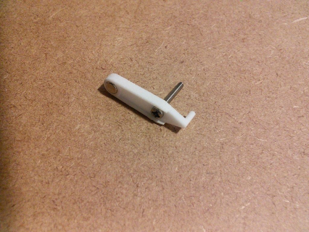
12. Now thread a stainless steel pan head machine screw, 2mm dia x 14mm long, through the other hole in the guide arm. Tighten until snug. The head of the screw should be flush with or recessed below the bottom edge of the guide arm.
Be sure not to over tighten this screw. Doing so will strip the threads cut by the screw and cause the screw to spin freely in the hole of the guide arm. If this happens use a drop of CA glue to prevent the screw from spinning in the arm. See photo below.
13. Now pick up the upper and lower beams with the attached wheels and carefully insert the pins of the tie rod into the holes in the knuckles.
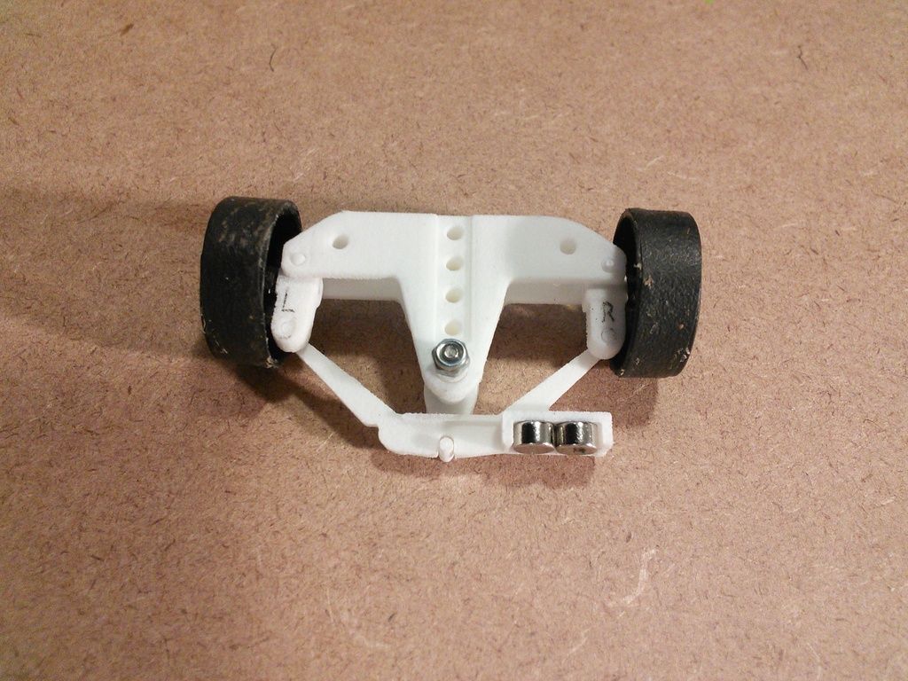
14. Attach the guide arm to the suspension beams with a stainless steel Nylon-Insert Locknut, which fits the machine screw that is attached to the guide arm. Take care inserting the pin on the end of the guide arm, into the slot in the tie rod. Use a screwdriver to prevent the screw from turning while the nut is tightened or loosened. When the beams of this assembly are held in a vertical orientation, and rotated back and worth, the tie rod should move freely allowing the wheels to turn left and right freely. A frontend assembly is pictured below.
Please contact me by PM, if you find a mistake in the instructions or have a suggestion for improving them.


