Part 6: Assembling Frontend Kit
Be careful working with any of the frontend parts with small pins/posts. The diameter of these pins is specified to be .070" in the 3D model. When printed by Shapeways the diameters usually range from .064" to .067". Most of these pins fit into a hole and must rotate freely. The holes have a specified diameter of .072". When printed they usually range from .068" to .070". To get the pins and corresponding holes to fit precisely, you have to enlarge most holes to fit the pins. It is best to enlarge the holes in small incremental steps rather than in one fell swoop.
1. Determine the correct orientation of the polarity of the two neodymium 4mm dia x 3mm thick magnets to be glued into the box on the tie rod. (Note that these magnets have a smaller diameter than the ones used in an original magracer.) It is important that the polarity of both magnets is oriented correctly, when glued into the box.
- A. If you have an operational stock magracer:
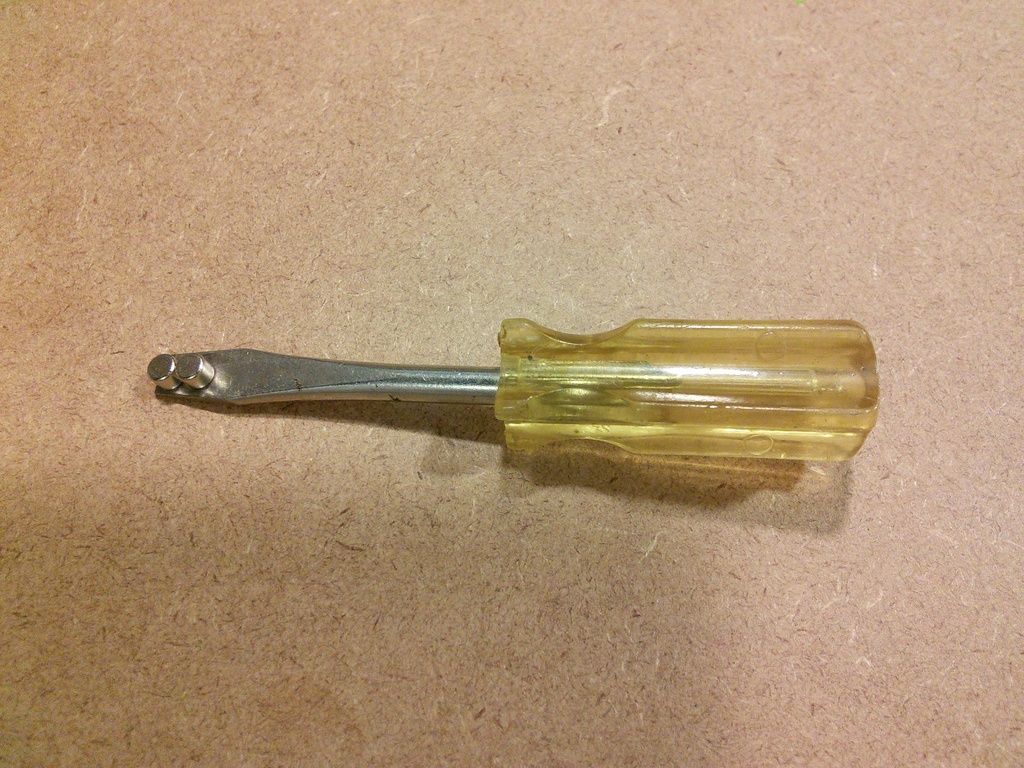
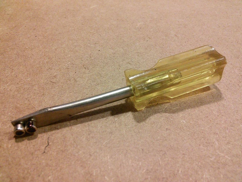
- 1. Place 2 magnets side by side on the blade of a screwdriver as depicted in the photo below.
- 2. Now with your thumb and index finger, take a hold of the magnet box on your stock magracer, and place the magnets stuck to the screwdriver against the back of the magnet box. If the magnets are oriented properly on the screwdriver, they will quickly snap toward the magnets in the stock magracer and easily line up as shown in the photo below.
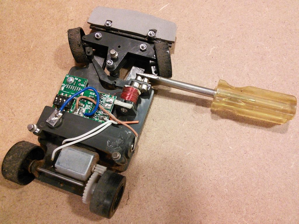
- 3. If they don’t want to line up easily, the magnets on the screwdriver are not oriented properly. Change the orientation and try again.
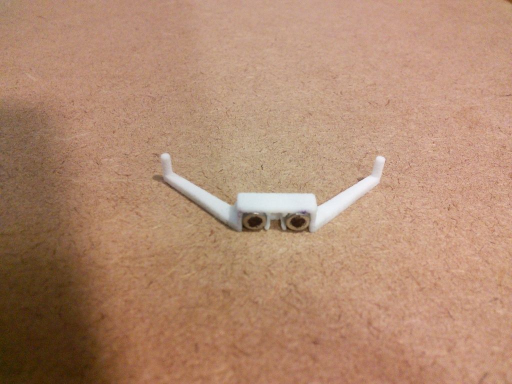
4. Once they are oriented properly, mark the exposed faces of the 2 magnets on the screwdriver with a black permanent felt tip pen. Also mark the top edge of one of the magnets to distinguish between left and right as shown in the photo below.
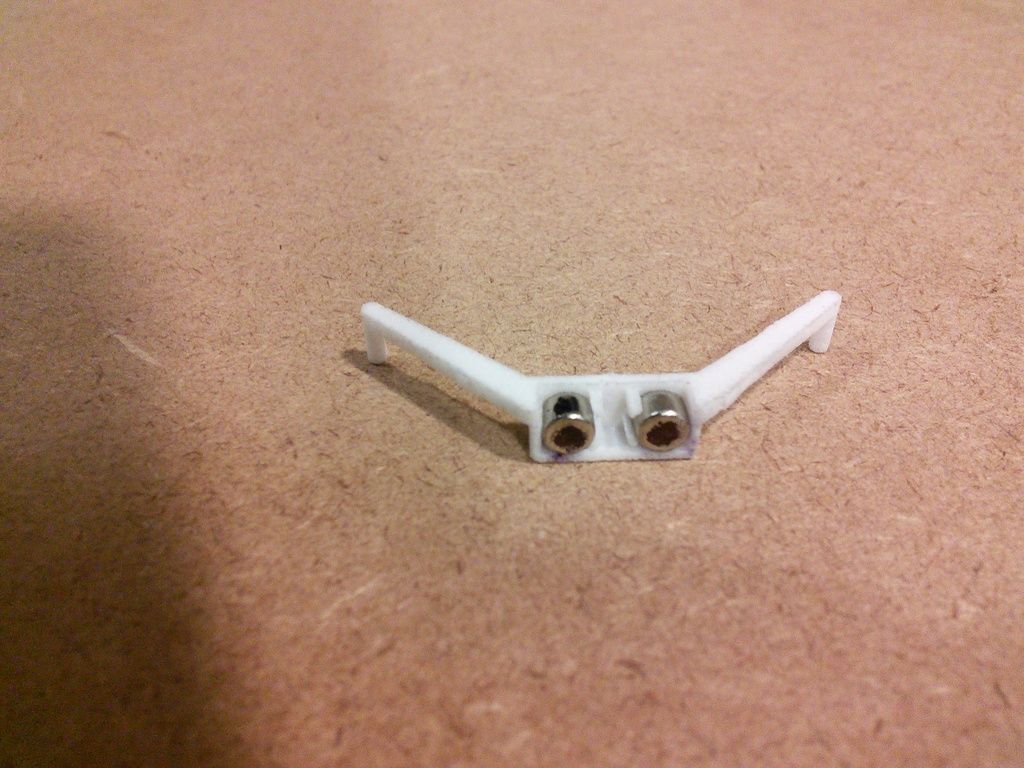
- 5. Now that you have determined the correct orientation for the magnets, glue them into the box on the tie rod. Make certain that they are both oriented the same way in the box as in the stock magracer, with the black faces facing as depicted in the photo below. Be careful not to switch the left and right magnets. When gluing the magnets in place, make sure that they are firmly pressed to the back of the box and into the cxorners. CA glue such as Krazy Glue or Supper Glue works well for this. Two part epoxy adhesive also works. When the glue is dry inspect the bottom of the tie rod. Remove any glue that may have oozed out on the bottom edge of the magnets or box.
Tie rod oriented rightside up.
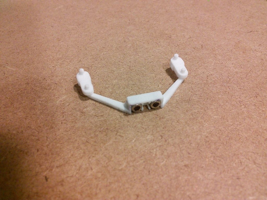
Tie rod oriented upside down.
- B. If you do not have an operational magracer:
- 1. You‘re in trouble

- 2. Not really! If you have a stock tie rod with magnets installed, use that as your model for comparison, and follow the instructions above.
- 3. If you don't have anything with which to compare, you have a 50% of getting it right! Just glue 2 magnets in the box. Make sure that they are firmly pressed into the corners of the box. CA glue such as Krazy Glue or Supper Glue works well for this. If they are oriented the wrong way, the car will steer the wrong way. In that case just swap the coil wiring on the PCB and you're good to go.

Be careful handling the stub axle carriers (steering knuckles) and steering plate (tie rod) so as not to break or bend the pins.
2. Ream out the hole farthest from the kingpins, in each of the stub axle carriers (steering knuckles) using a #50 (.0700” diameter) (1.78mm) drill bit held in a pin vice (small handheld manual drill). (The steering knuckles are symmetrical and the 3D model for the left one is identical to the right one.) Now check to see if the pins at each end of the steering plate (tie rod) will fit into the holes that you just enlarged in the steering knuckles. An easy and safe way to do this is to first place the tie rod on a smooth flat surface, with the pins facing up. Then with the finger of one hand, hold down the tie rod. Now with the thumb and index finger of the other hand, (or a pair of tweezers) grasp a knuckle near the hole you enlarged. Slip the hole in the knuckle over the pin on the tie rod. Be very careful doing this so as to not break the pin off of the tie rod. A pair of tweezers comes in handy for this. Do NOT try to force the pin into the hole. Do the same with the other knuckle and pin.
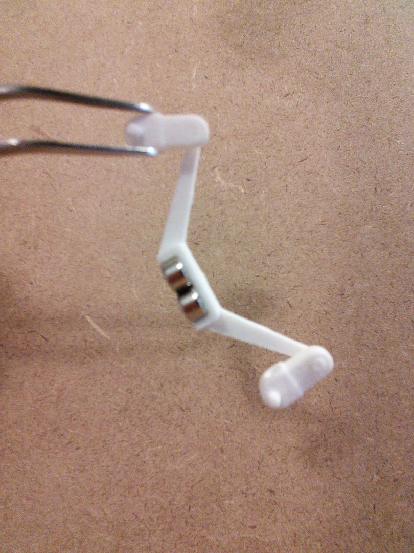
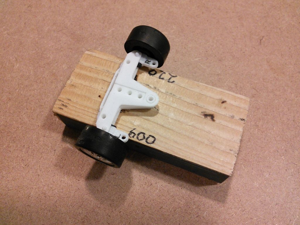
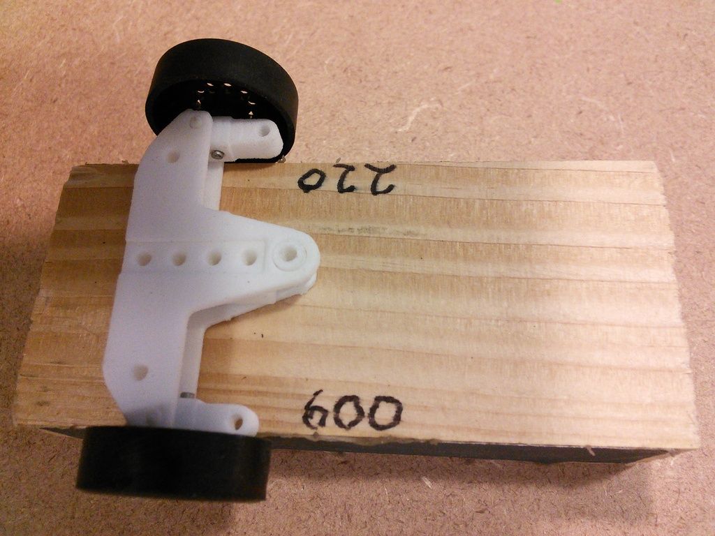
3. The knuckles should rotate freely on the pins of the tie rod but without any play (without any slop). If they don’t rotate freely, ream out the hole a little more with the same #50 (.0700") (1.78mm) bit. Do not use a bit larger than #50. The best hole diameter is usually about .003” larger than the pin diameter. When the knuckle is held as shown, the tie rod should should swing freely and come to rest as depicted in the photo below.
4. Now put the upper and lower suspension beams together.
Simultaneously ream out the holes at the end of the beams with a .075” diameter(1.90mm) bit. See photo below.
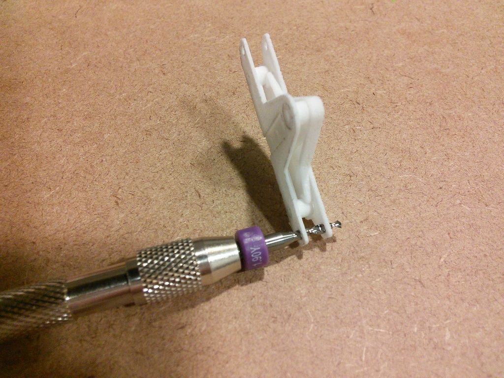
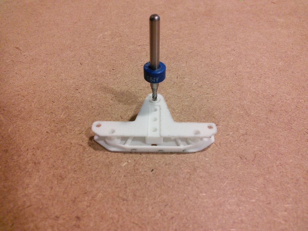
5. After that, with the upper and lower beams still held together, ream out the hole in the lower beam that is used to attach the guide arm to the beams. Use a 5/64” diameter (.0781) (1.98mm) drill bit held in a pin vice to do this. See photo below.
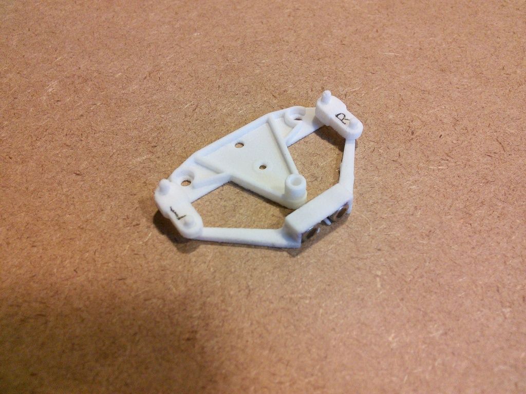
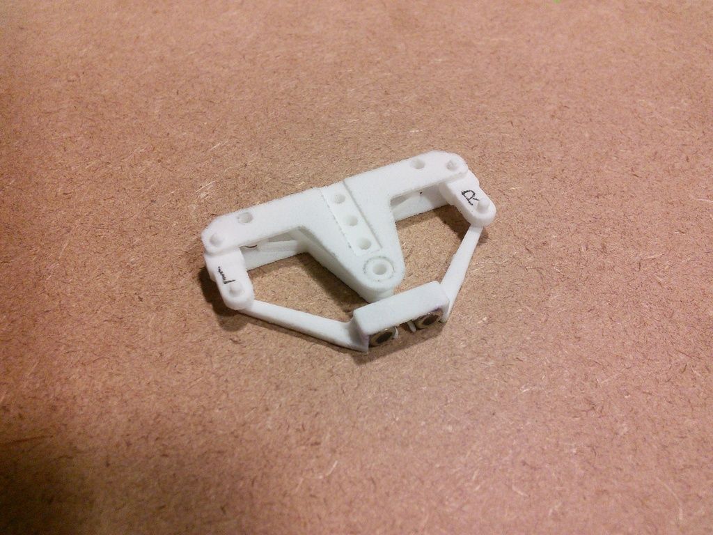
6. Now separate the upper and lower suspension plates (beams) and check to see if the king pins of the steering knuckles fit into the corresponding holes at the end of the lower suspension beam. An easy way to do this is to first place the lower beam on a smooth flat surface. With the steering knuckles attached to the tie rod, place the pin of one of the knuckles, into one of the holes at the end of the lower beam. Do the same with the other knuckle. Label the knuckles Left and Right so you can put them back together the same way.
7. Now place the upper beam over the lower beam and knuckles, being careful to align the pins of the knuckles with the holes in the upper beam. Press the lower and upper beams together. The knuckles, with the tie rod attached, should rotate freely between the beams when the beams are squeezed together in the middle. If they don’t, remove the knuckles, put the upper and lower beams back together again, and ream out the holes again at both ends
simultaneously with a #48 (.760”) (1.93mm) bit and try again.
When reaming out the holes at the ends of the beams, only do so when both beams are held together so that the holes in the upper and lower beams can be reamed out simultaneously to maintain the proper alignment.
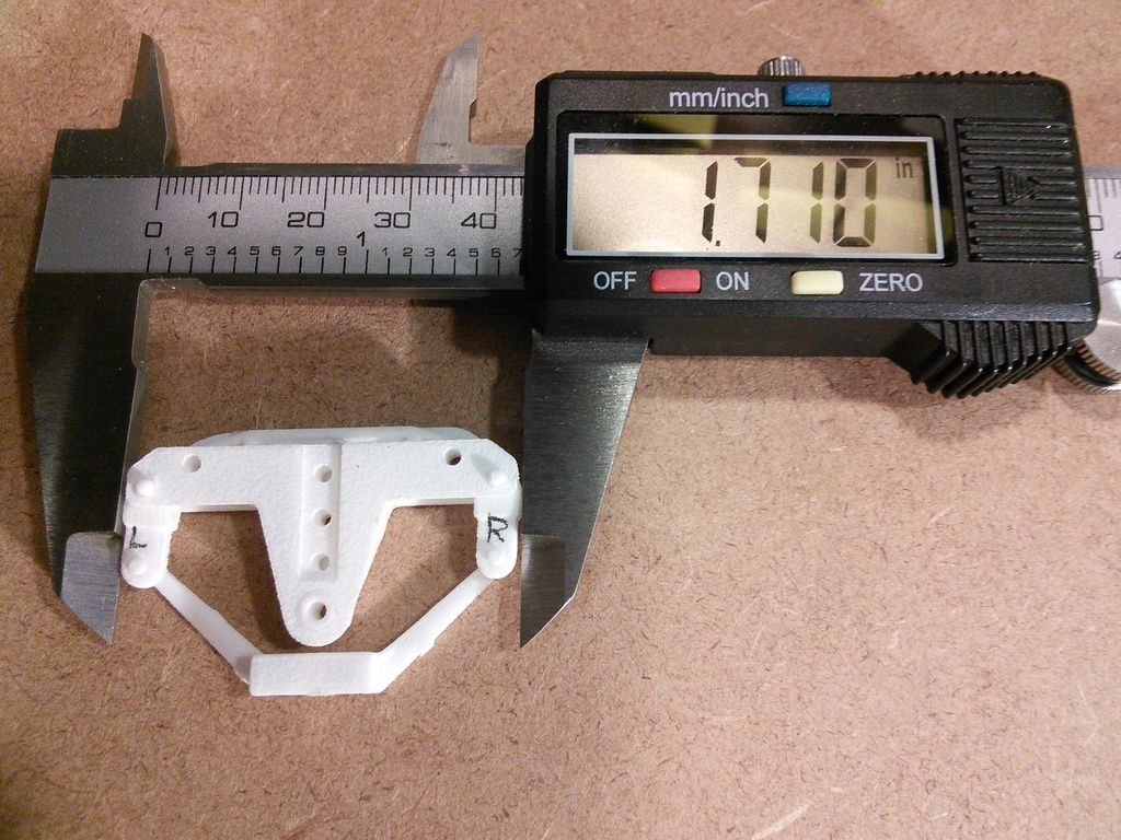
8. Determine how wide your front wheels (including the hub) have to be to fit your body appropriately. Measure the width of your body at the front wheel wells. In the example here, the body is 2.42” wide at the front wheel wells. Now measure the distance between the steering knuckles. It should be about 1.71” as seen below in the photo. Subtract the 1.71” from 2.42” to obtain .71”. Now divide by 2 to get .355”. Subtract side clearance of .005” from .355” to arrive at .350”. This is the ideal width of the front wheels including the hubs (with tire mounted).
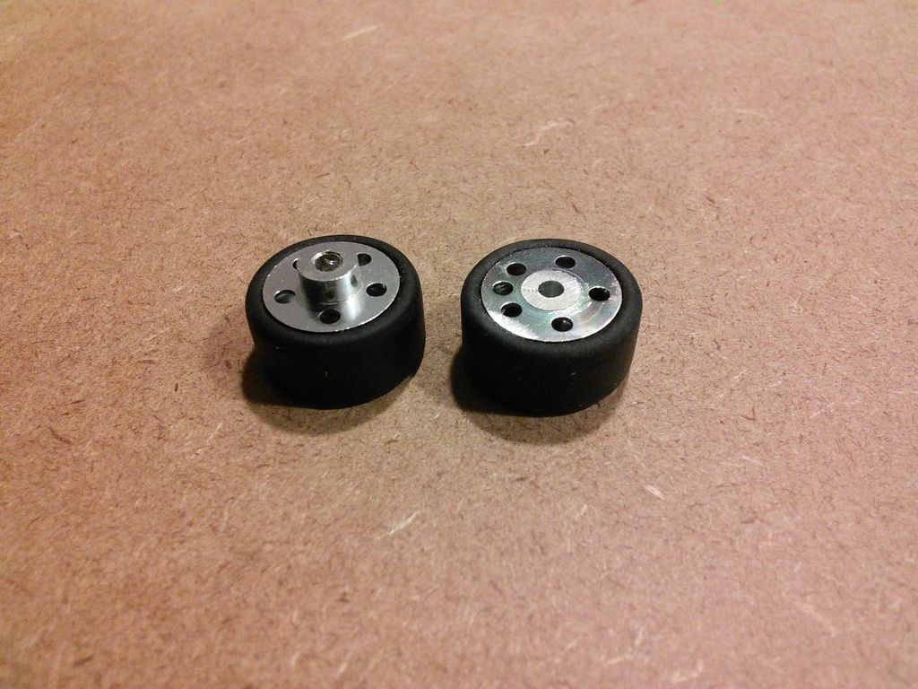
9. If the original wheel (with the hub) is too wide, reduce the length of the hub as needed. This is common. If the wheel is made of plastic, it is easy to shorten the hub by sliding the hub back and forth over #200 sandpaper. If it is too short, you will have to put a spacer between the end of the hub and the steering knuckle to increase the front track. The photo below shows 2 aluminum wheels, one with the hub shortened by sliding it back and forth over a piece of #120 grit sandpaper on a smooth flat surface.
8. Now disassemble the beams, knuckles, and tie rod, being careful not to bend or break any pins.
9. At this point the appropriate instructions depend upon whether you intend to have your front wheels a) spin on fixed stub axles, like a stock magracer or b) not spin on stub axles which themselves spin in the steering knuckles, as is common for some 1/32 slot cars.
Avoid pinching the king pins on the steering knuckles, so that you do not bend or break one. A pair of tweezers comes in handy here.
- a) If you intend to have your front wheels spin on fixed stub axles, like a stock magracer
- 1. Make sure that your stub axles are the appropriate length. The distance between the front wheels can be reduced by shortening the wheel hub. The distance can be increased slightly by putting a spacer on the stub axle between the wheel hub and the steering knuckle.
- 2. Verify that your wheels spin freely, without wobble on your stub axles. If not, correct before proceeding. I recommend that you glue your tires onto your wheels and then sand as needed to make them perfectly round. The diameter of the hole in the wheel should be about .002” larger than the diameter of the stub axle.
- 3. Locate the hole for the stub axle in each steering knuckle. Ream out those holes so that they are about .001” smaller in diameter than the stub axles. If you are using 3/32 stainless steel rivets for stub axles (which measure .095”) , a 3/32” (2.38mm) drill bit should work fine. If you are using 2.50mm machine screws for stub axles , (which measure .096”) a #41 (.0960”) (2.44mm) drill bit will probably be okay.
- 4. From the outside of the wheel, slide a 3/32” or 2.5 mm stub axle through the bore of a front wheel. Now place a washer/spacer on the protruding axle, if needed to increase the distance between the front wheels. Then, if a rivet, press the end of the stub axle into the hole in the Left or Right steering knuckle, as appropriate. If a machine screw, screw it into the appropriate knuckle. Leave about .005” of side play so that the wheels will spin freely on the stub axles.
- b) If you intend to have your front wheels NOT spin on stub axles
- 1. Locate the hole for the stub axle in each steering knuckle. Ream out those holes so that they are about .004” larger in diameter than the stub axles. If you are using 3/32 stainless steel rivets for stub axles (which measure .095”) , a #40 (.0980”) (2.50mm) drill bit should work well. For 2.50mm machine screws, try a #39 (.0995") (2.53mm) drill bit, then #38 if needed. When enlarging the hole, do it in steps starting with a 3/32" bit and gradually increasing the diameter as needed. Beware, don’t squeeze the pins on the knuckles when reaming out these holes.
- 2. Reduce the diameter of the head of your stub axles to less than .125” (3.18mm) and the head thickness to less than .035" (.89mm). Grinding steel rivets down with a Dremel is fairly easy but time consuming. The head diameter can be quickly reduced by spinning the head against a file using an electrically powered drill. The plastic stub axles that come with many Fly slot cars work very well. It is very easy to change the length and head dimensions of these by sanding.
The 3/32" diameter stainless steel rivet on the left was used to make the stub axle on the right. The length, head diameter, and head thickness were all reduced. The stub axle will be presssed into the wheel. Then the plastic wheel insert will be pressed on to the wheel.
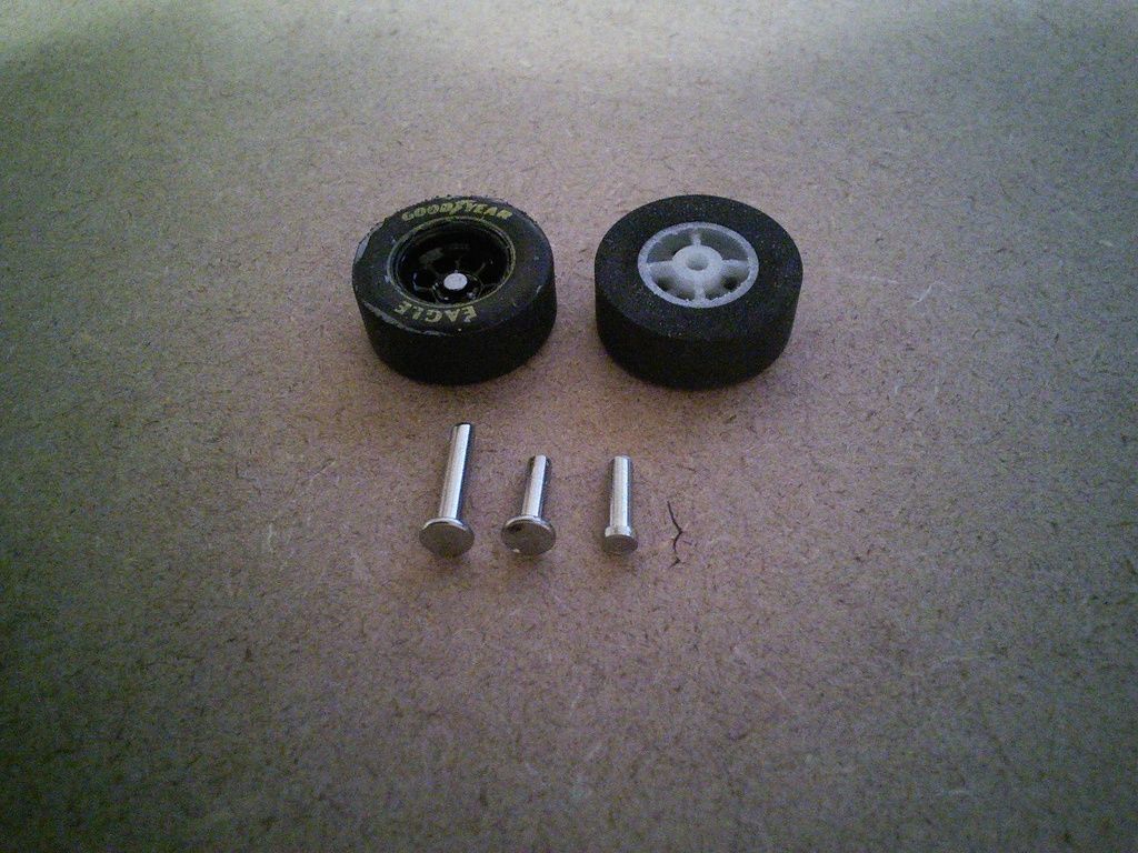
A stainless steel rivet like the one on the left was used to make the stub axle on the right to fit the wheel, after the width of the wheel and tire had been reduced by sanding.
- 3. Make sure that your stub axles are the appropriate length. The distance between the front wheels can be reduced by shortening the wheel hub. The distance can be increased slightly by putting a spacer on the stub axle between the wheel hub and the steering knuckle. Assuming you are not using any spacers to increase the front track, the length of the stub axles under the head should be equal to the length of the hole in the steering knuckle (.205”), + the depth of the hole in the wheel hub + .005" for a little side play.
- 4. Verify that your wheels do not wobble when spinning on a 3/32" axle or drill bit. Also verify that the stub axles spin freely in the steering knuckles, first without, and then with the wheels attached. Also . Correct any problems before proceeding. Consider gluing your tires onto your wheels and then sanding as needed to make them perfectly round.
- 5. Slide a 3/32” or 2.5 mm stub axle through the hole in the Left or Right steering knuckle, as appropriate. Now place a washer/spacer on the axle, if needed to increase the distance between the front wheels. If a rivet, press the end of the axle into the hub of a wheel. I do not recommend gluing wheels to the stub axles with CA glue because you probably won't be able to adjust or separate them. If using a machine screw, screw it into the hub. Leave about .005” (.127mm) of side play so that the wheels will spin freely.
10. Attach the knuckles, with the front axles and wheels, to the upper and lower suspension beams. An easy way to do this is to place the lower beam across a block of wood 1.5” wide and about ½” thick and 3” long. Place the bottom pin of each knuckle in a hole at the end of the beam. Then place the upper beam on top making sure to line up the pins of the knuckles with the holes in the beam. Press the upper and lower beams together with the steering knuckles and wheels attached and set this aside.
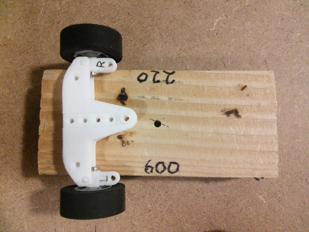
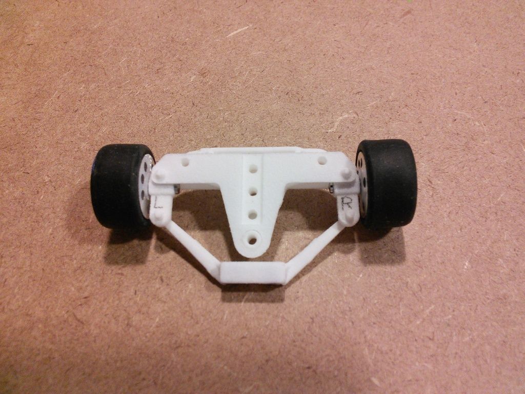
The photo above is one of a frontend assembly using front wheels from a SCX slot car and method b, with spinning stub axles made from stainless steel 3/32" rivets.
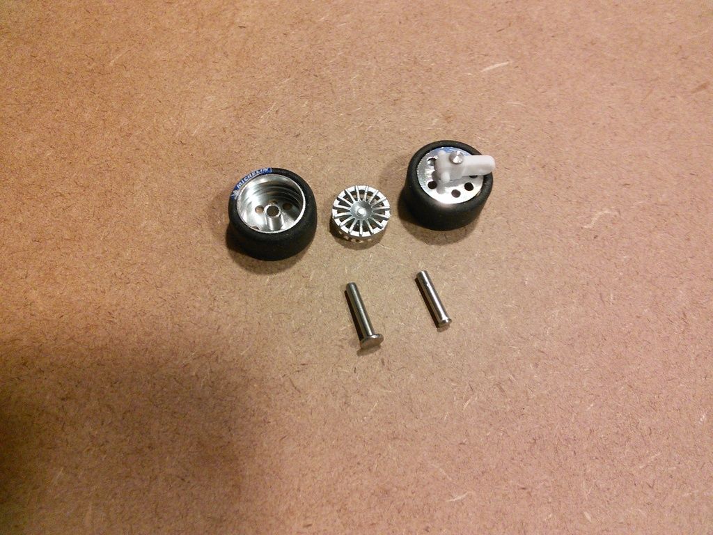
The photo above is one of a frontend assembly using front wheels and plastic stub axles from a Fly slot car. The stub axles spin in the steering knuckles.
The photo above is one of a frontend assembly using stock front magracer wheels and method a, with fixed 1/16" diameter stub axles.
Be careful handling the guide arm so as not to break or bend the pin.
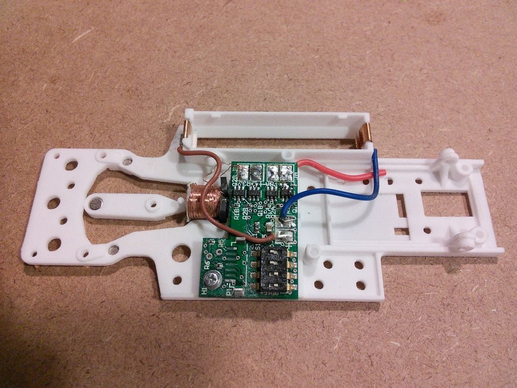
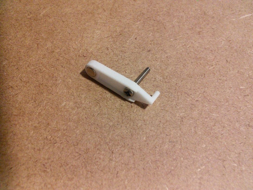
11. Now press a neodymium 4mm dia x 3mm thick magnet into the guide arm. Make sure that the magnet is oriented so that the polarity is the same as that of the two 3mm dia x 2mm magnets pressed into the frame earlier. All 3 magnets must be orientated the same way, either all with the positive (+) pole facing up, or all with the negative (-) pole facing up. If oriented correctly, the magnet in the guide arm will be repelled by the magnets in the frame, so as to naturally center the magnet in the guide arm in the large hole in the frame, as depicted in the photo below. The bottom of the magnet should protrude about .010” - .015” below the bottom of the guide arm. A 4mm x 3.25mm magnet should also work.
12. Now thread a stainless steel pan head machine screw, 2mm dia x 14mm long, through the other hole in the guide arm. Just before snugging the head down on the guide arm, apply a drop of CA glue under the head. Now tighten until snug. The head of the screw should be flush with or recessed below the bottom edge of the guide arm. See photo below.
13. Now pick up the upper and lower beams with the attached wheels and carefully insert the pins of the tie rod into the holes in the knuckles. Do not attach the guide arm at this time.
Please contact me by PM, if you find a mistake in the instructions or have a suggestion for improving them.


